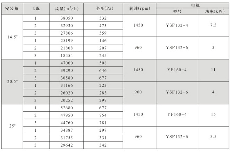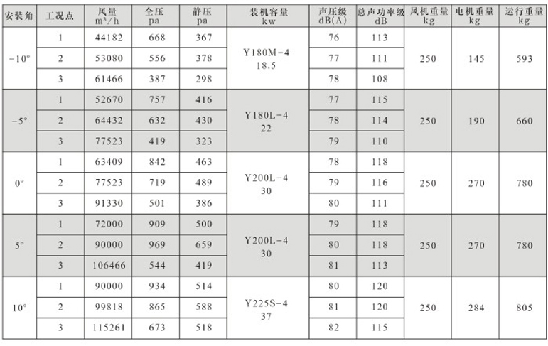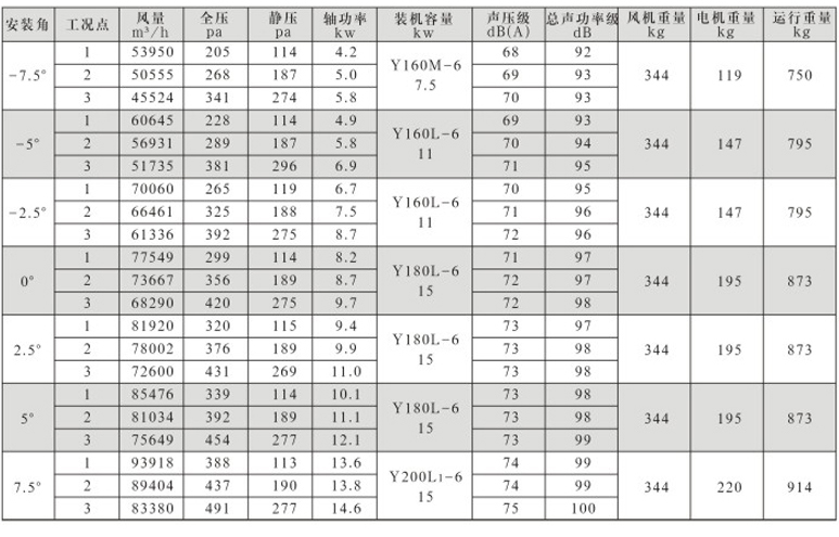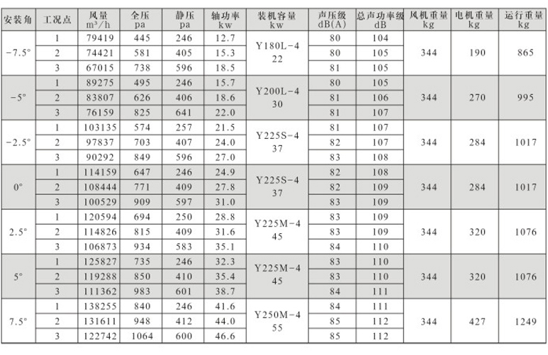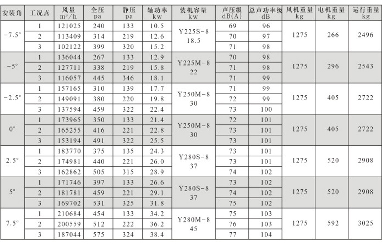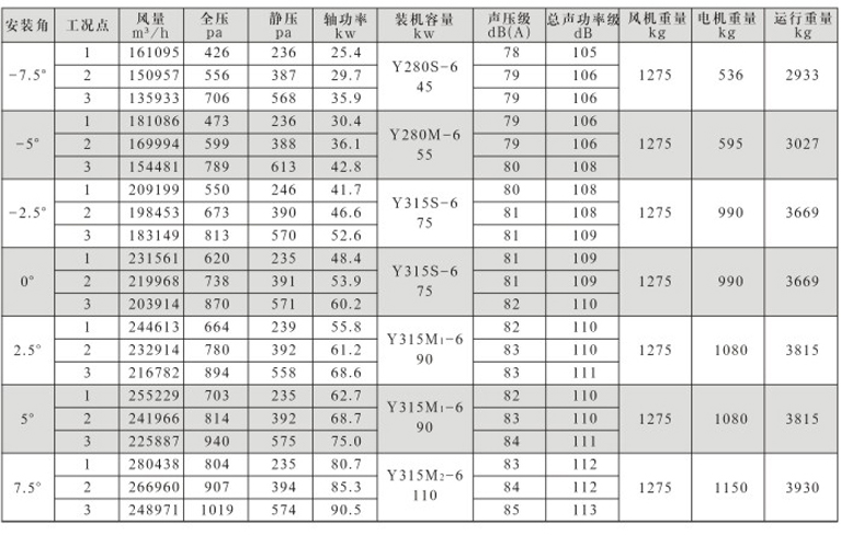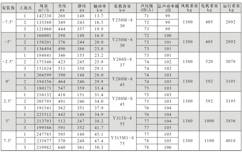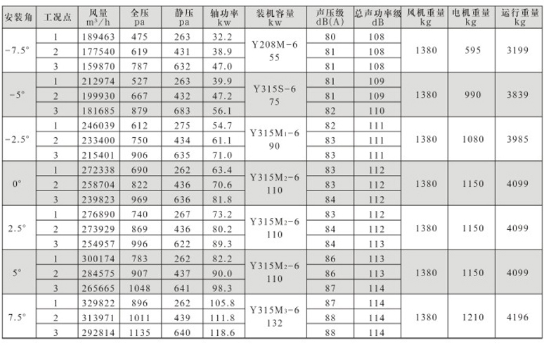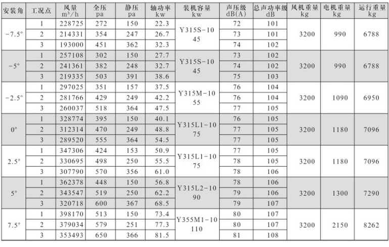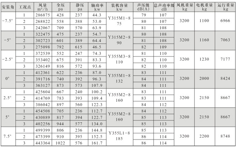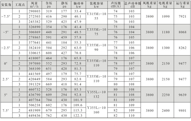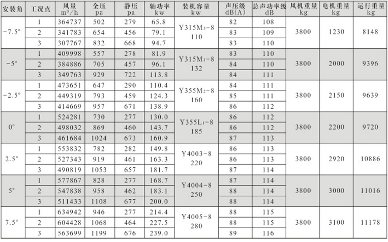
Product Specifications
Features: The fan is designed in accordance with international aerospace aerodynamic requirements. Through repeated tests and verification, as well as user feedback, it has been proven to have remarkable characteristics such as high efficiency, a wide high-efficiency range, and similar efficiency in both forward and reverse rotations.
Uses: Axial Flow Fan Dedicated for Subway Tunnels
Specifications:
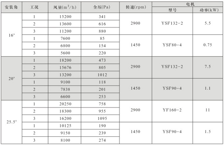
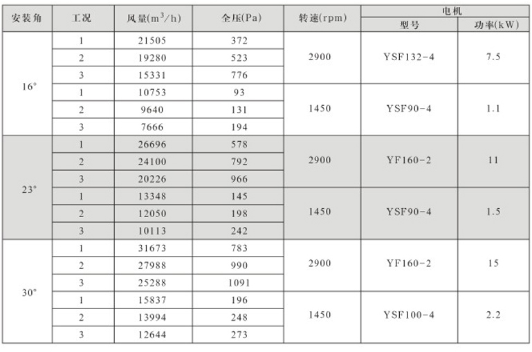
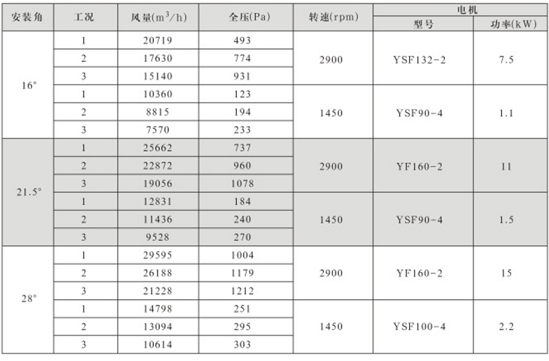
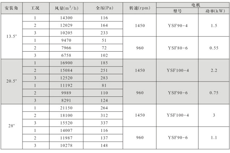
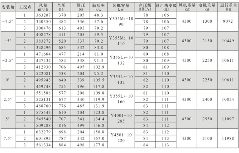
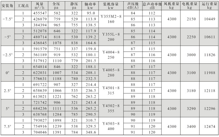
Ventilator diameter: Φ1250~2800mm,
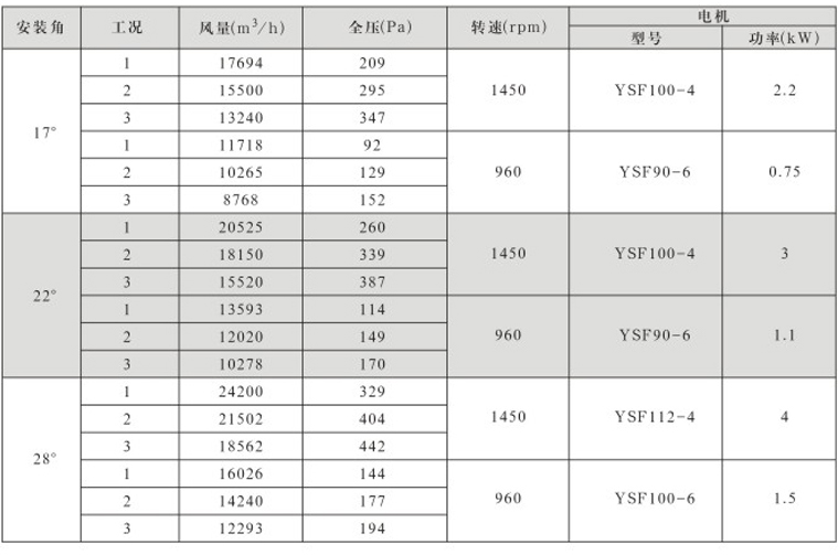
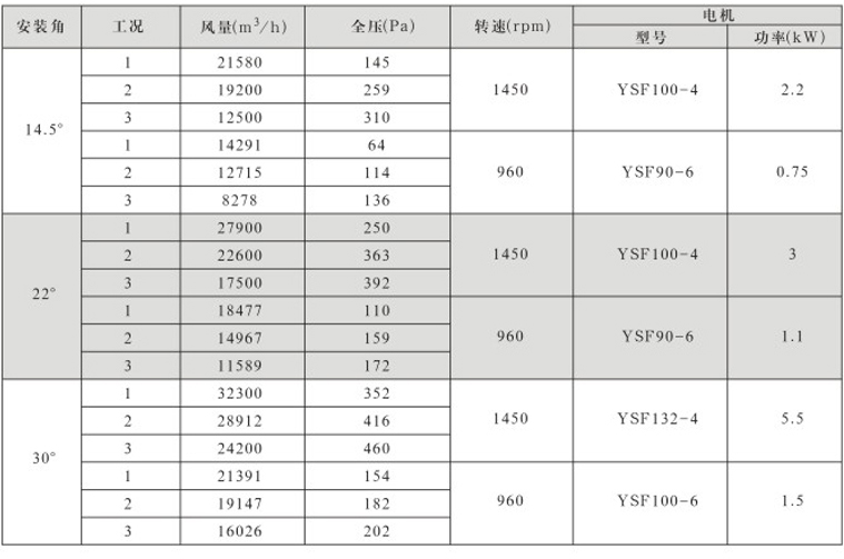
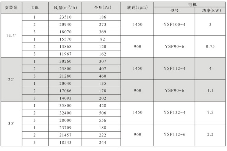
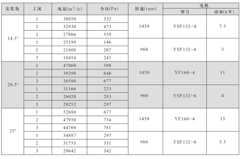
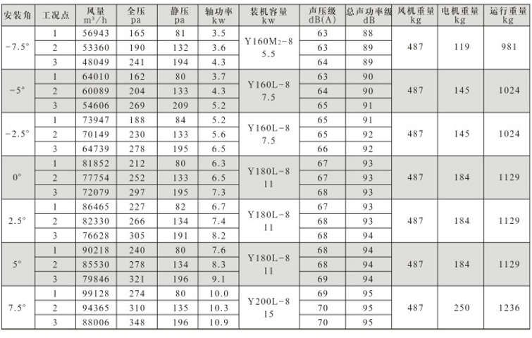
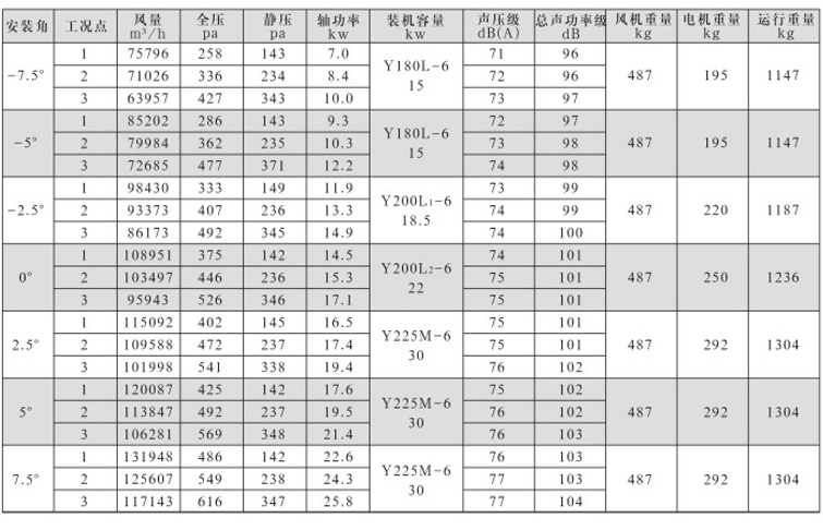
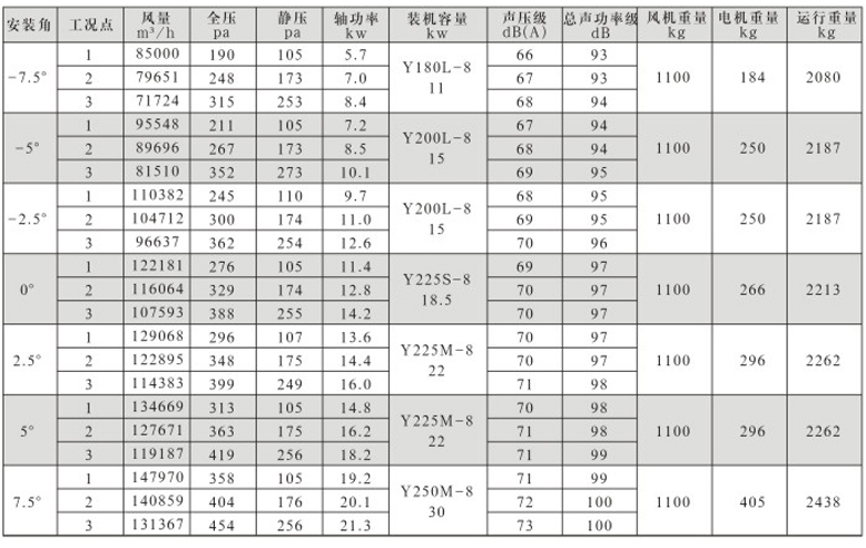
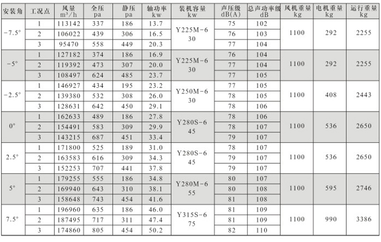
Air volume: 53950~793027m³/h,
Wind pressure: 205~1391Pa
Product Overview
With more than 20 years of experience in professionally developing special-purpose fans, Shangyu Ventilator has, based on thorough research and on-site investigations of subway ventilation systems in Beijing, Shanghai, Hong Kong, and other domestic and overseas locations, collaborated with Beihang University and Shanghai Jiao Tong University. By applying the experimental mechanisms from the China Aerodynamics Research and Development Center and the laboratory of the China Aviation Gas Turbine Research Institute, and through extensive tests on fan passage vortex systems, a digital model for the fan was established. Repeated calculations and meticulous design were conducted to minimize harmful vortex systems at the blade tips and roots, achieving the goals of high efficiency, low noise, compact structure, and reliable operation.
On the basis of absorbing international advanced technologies and with the enthusiastic assistance and guidance of experts from domestic subway and tunnel design institutes, Shangyu successfully developed high-quality fans dedicated to subways and tunnels. The DTF(R)(R) series fans (TVF fans) have been verified by domestic authoritative experts and practical user applications to have remarkable characteristics, including high efficiency, low noise, short forward/reverse rotation switching time (<30 seconds), high-temperature resistance (qualified by national testing centers), compact structure, and stable operation. Experts unanimously agree that they have reached international advanced levels. Shangyu Ventilator has also introduced and specially developed new technologies for air pressure randomly adjustable fan blade angles and new products of anti-surge devices to further adapt to the usage requirements under specific conditions of subways and tunnels.
The fan applies brand-new international aerospace aerodynamic design technologies. Through repeated tests and user applications, it has been proven to feature high efficiency, a wide high-efficiency range, and similar efficiency in both forward and reverse rotations.
Starting from reducing the aerodynamic noise of the fan, it minimizes the vortex loss at the tips and roots of the fan blades to the greatest extent. Verified by experiments, applications, and authoritative experts, it has the significant characteristic of low noise.
According to the usage requirements of subways and tunnels, Shangyu Ventilator uses anti-corrosion, moisture-proof, high-insulation-grade, heat-moisture-type, and high-temperature-resistant motors, enabling the fan to be reliably applied to ventilation (exhaust) in subway and tunnel ventilation systems and to fire smoke exhaust systems in emergency situations (capable of continuous operation for 45 minutes at 280°C and more than 1 hour at 180°C).
The fan impeller system introduces international advanced pressure casting process technology. The aluminum alloy blades and hub have good structural organization through metallographic analysis and pass X-ray flaw detection. The expansion coefficients of the fan impeller and air duct under the condition of 280°C have been considered, ensuring sufficient impeller strength to meet the requirements of high-speed operation.
The design of the fan's stationary vanes and guide devices aims to shorten the length of the fan casing as much as possible. The casing and fixed supports undergo finite element strength calculations to meet the usage requirements of specific subway conditions.
The fan adopts an energy-consuming stopping method. Repeated tests have proven that the time for the fan to switch between forward and reverse rotations and reach the rated speed is less than 30 seconds.
The fan casing is treated with hot-dip galvanizing, the motor is of heat-moisture type, and the fan blades and hub are made of aluminum alloy materials with surface anodization treatment, featuring strong corrosion resistance.
The fan impeller is precisely calibrated by a Sino-foreign joint venture dynamic balancing machine and tested by the automatic testing system of the National Fan Technology Research Center of Shanghai Jiao Tong University, with its balance accuracy reaching ISO-2.8 level (higher than the national standard of 5.6). Before leaving the factory, the fan undergoes impeller overspeed tests, overall vibration tests, and full aerodynamic performance tests to meet the requirements of stable and reliable operation.
For this series of fans, the national fire protection inspection department sampled a 12.5# fan and sent it to Shanghai for high-temperature resistance tests. The tests proved that after operating for 45 minutes at 280°C and for 1 hour at 180°C, the fan can continue to run.
The fan is equipped with an anti-surge device, which can prevent the fan from surging and ensure long-term stable operation, especially guaranteeing safety and reliability under tunnel emergency conditions.
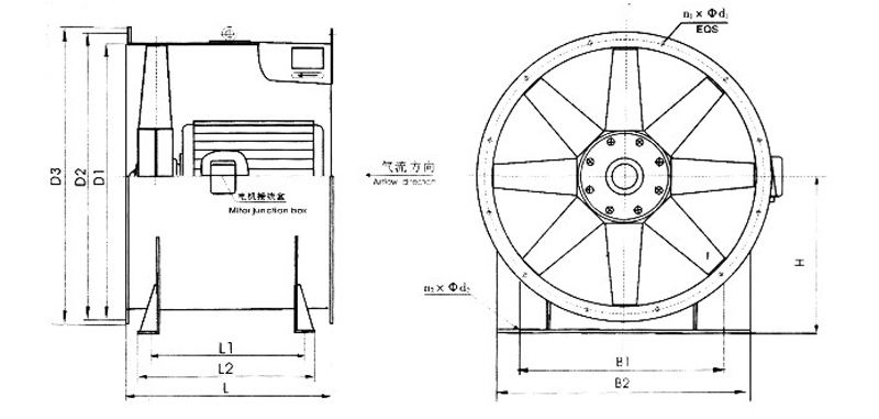
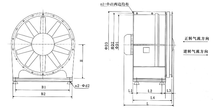
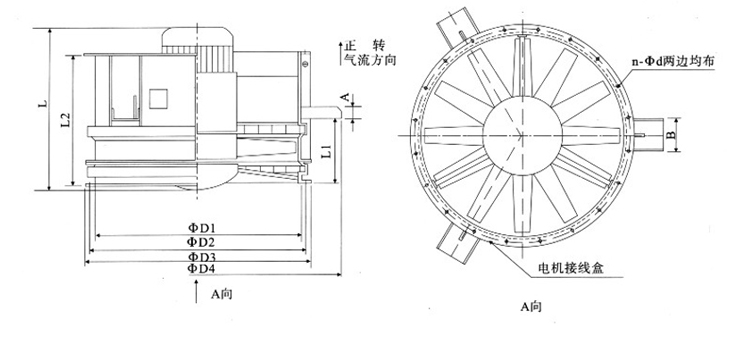
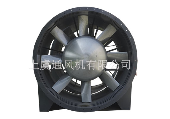
The fan is composed of components such as an impeller, motor, casing, collector (guide) vane, guide vanes, anti-surge device, fixed supports, and shock absorbers, and is available in two installation forms: horizontal and vertical.
Composed of a hub and blades, the fan blades are divided into three adjustment methods: fixed, dynamic adjustment, and static adjustment. The static or dynamic adjustment blades can be adjusted within the range of -7.5° to 7.5°. Dynamic adjustment fans are further divided into pneumatic and electric types, which can adjust the blade angle under continuous operation.
Adopts IP55 (IP54) protection grade, H (F) grade insulation, and heat-moisture type motor. The bearings supporting the motor use SKF fully enclosed motor ends. The junction box is installed on the fan casing.
The inner wall is machined to ensure control of the radial clearance of the blades, and the length and weight are designed to be minimized.
They are respectively installed statically to consider maximum efficiency and minimum volume as much as possible.
On the premise of ensuring the overall strength of the fan, it meets the requirements of light weight and convenient installation.
Fixed impeller: The impeller and blades are fixed.
Static adjustable: After stopping the machine, loosen the blade root bolts and manually adjust the blade angle.
Dynamic adjustable: Arbitrarily adjust the blade angle according to the usage conditions during the fan's operation, and automatically control and adjust the blade angle according to temperature and humidity requirements.
Anti-surge Device
Prevents the fan from surging, ensuring long-term stable operation, especially guaranteeing safety and reliability in tunnel emergency states.
Fan Forward/Reverse Rotation Switching Device
Installed in combination with the fan's electrical control system, it features short switching time (<30 seconds), convenient installation, and strong reliability.
Fan Shock Absorbers
Installed between the bracket and the base. Due to different dynamic loads, fans with fixed blade angles and dynamically adjustable blade angles use different shock absorbers, which are specially designed and calculated for configuration.
Fan Disassembly and Maintenance Method
First, remove the flexible pipes at both ends of the fan (push them into the fan section or diffuser section) and the space section at the fan end, then loosen the fixed anchor bolts, and the fan can be moved arbitrarily for maintenance.
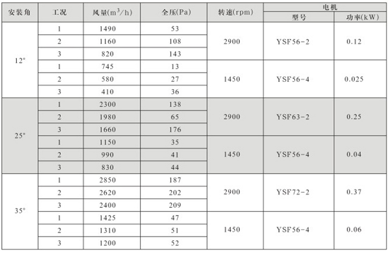
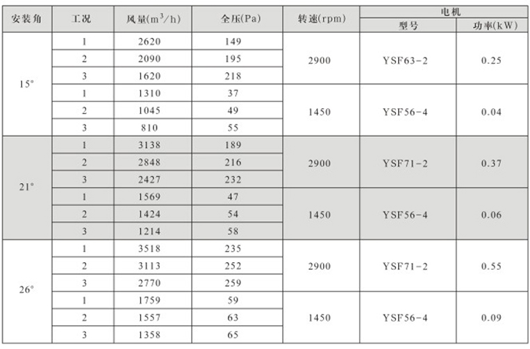
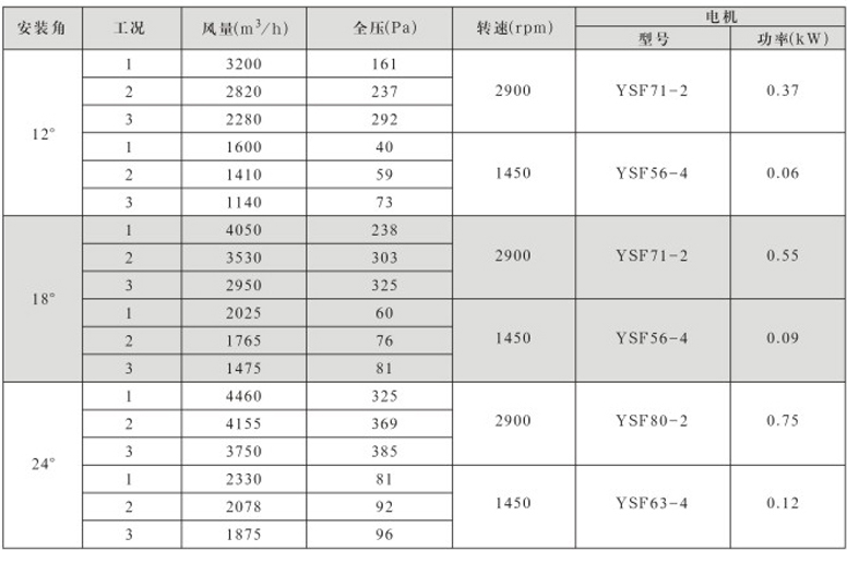
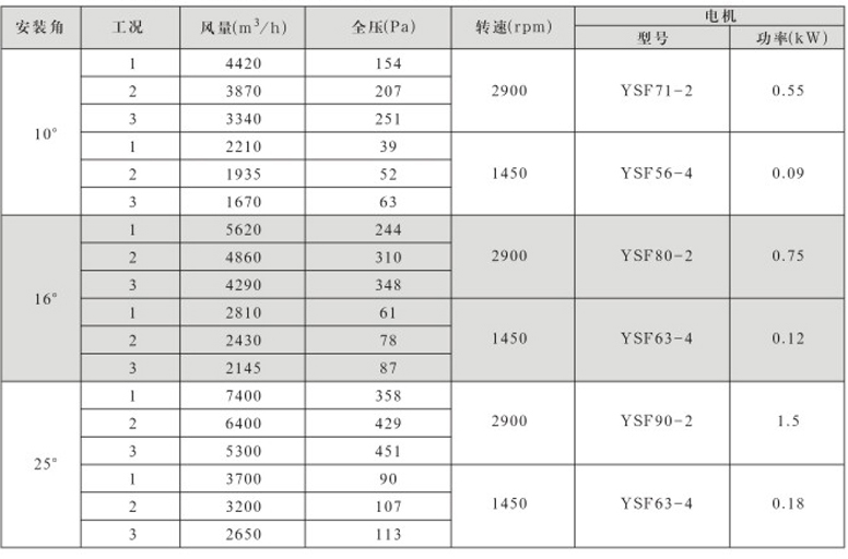
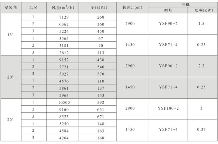
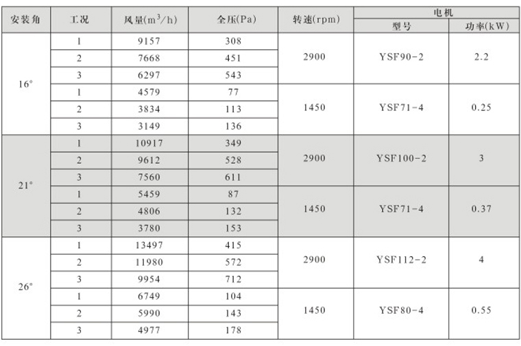
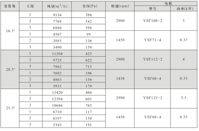
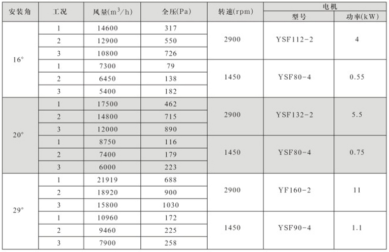
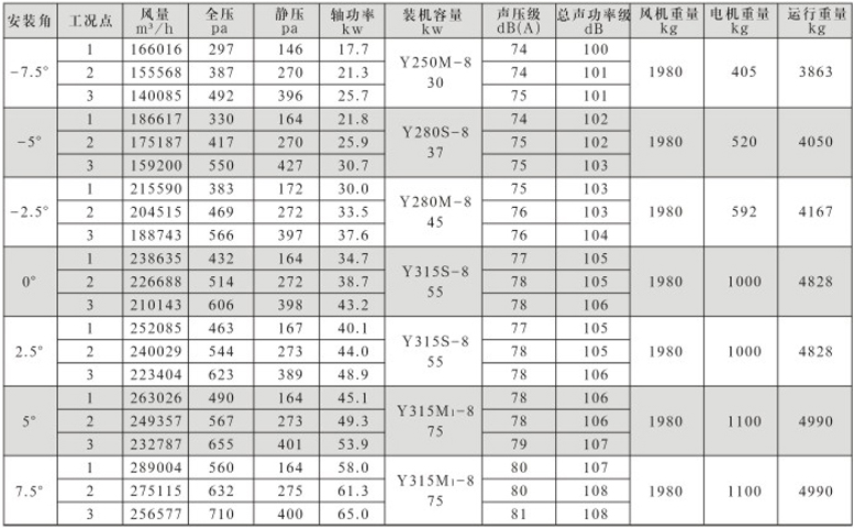
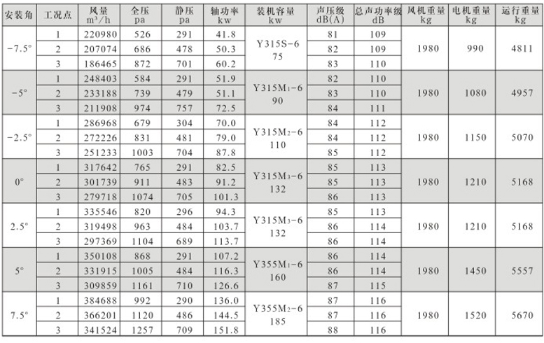
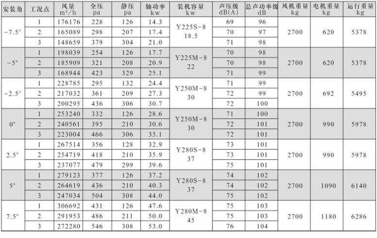
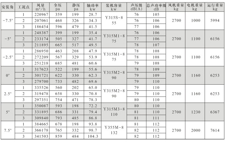
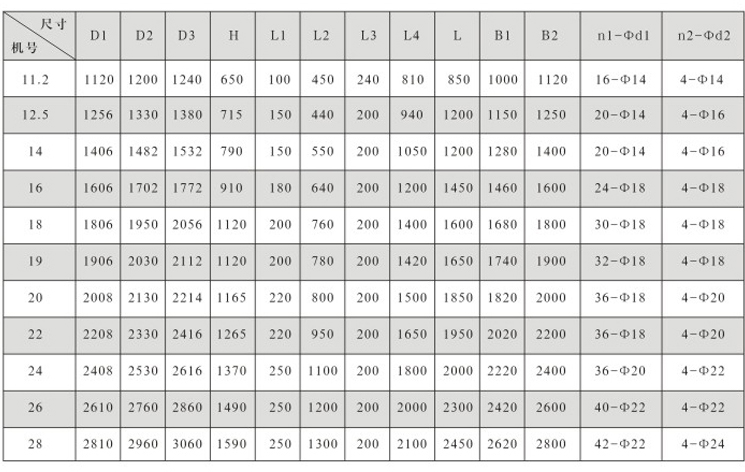
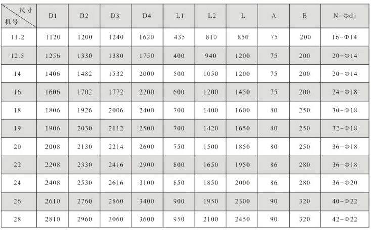
Product Parameters and Description
